
 en
en de
de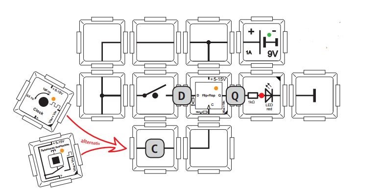
Flipflops for dummies – part 3
For those of you who enjoyed our blog post series “For dummies”, this new post is the right choice. Being a complete beginner myself, I will deal with RS flip-flops, D flip-flops and JK flip-flops today. As the topic of “Logic” is quite complex I advise you to read the former blog posts about Logic first that involve main logic gates and that give an overall explanation about flip-flops.
„Defined“ – The D Flip-flop
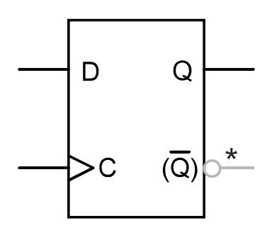
The D flip-flop consists of an RS flip-flop that has a reset input connected to the set input via an inverter. If you already read the blog post “Flip-flop for dummies – part 2”, you probably know what this means: There won’t occur an undefined state. We’ve already learned that an undefined state is unconvenient as the visual “rocker” does not know which side to tip. This is why coincidence decides whether the right end is up or down. A D flip-flop can be either state-controlled or edge-controlled. The brick in our Logic set is an edge-controlled flip-flop. In the following picture, you can see the circuit symbol (note that our D flip-flop brick does not have a /Q output):
II’s logical – the truth table
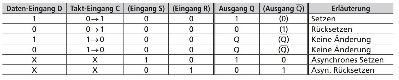
As with the RS flip-flop, we can illustrate the D flip-flop’s performance according to a so called truth table. With regard to the brick circuit, this means that there is a 1 at the data input D for pushing the button, meaning the connection will be ended. At the output Q there is a 1 for the illuminated LED. The 0 at the data output represents not pushing the button and the LED does not lighten up in the truth table at the output Q when there is a 0 indicated.
Let’s talk about clock input C now: if the state at input C changes from 0 to 1, there can be a change at the output Q. If the state at input C changes from 1 to 0, though (meaning we don’t push the button) there won’t be any changes at the output Q, no matter whether there is a 1 or 0 at the input D.
Reversely, this means, it does not matter what is at input D, whether I push the button 30 times or whether I don’t. As long as there isn’t a change from 0 to 1 at input C, there won’t happen anything. Exept a button at the input C you can also do a clock generator which is nothing else than a virtual finger that pushes the button in specific intervals. It displays 1 or 0 in the same intervals. The frequency is measured in hertz. The truth table also indicates additional optional inputs S and R and the output /Q. As our brick does not possess these, we don’t need to bother about them. In order to rebuild the truth table you should build the following brick circuit:

We will be dealing with the truth table in more detail and will look into D flip-flops with asynchronous set and reset input in our next blog post.